Even the simplest electrical circuit consists of several tools and devices. Figure 54 shows an electrical circuit consisting of a current source, a switch, an ammeter, a lamp, and a rheostat. Electricity from the source is passed through a switch, ammeter, lamp and rheostat. Such a connection of instruments serial connection is called. We learn to connect in series. 1. Current in a series-connected circuit. The current is the same at any point in the chain where the instruments are connected in series. If it were not so, the electric charges would have accumulated somewhere. It’s like a water mains: how much water flows from one place to another. so much water must flow from elsewhere.
It is possible to be sure experimentally that the current is the same at all points in the chain. We connect ammeters to different parts of the chain connected in series. This is shown in Figure 55 using three ammeters. These ammeters show the same current.
And so,
I1 = I2 = I3 =… In . (Formula 1)
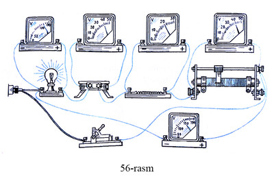
2. Voltage in a series-connected circuit. Assemble the electrical circuit shown in Figure 56. The readings of the voltmeters connected to the lamp, heater, coil and rheostat are different. Ammo U1, SHE IS2, SHE IS3 va U4 adding the voltages, we see that their sum is equal to the total voltage:
U1 + U2 + U3 + U4 = U.
Not four consumers n even when the consumer is connected in series, the voltage in the whole circuit is equal to the sum of the voltages in the individual parts:
U = U1 + U2 + U3 +… Un .(Formula 2)
Thus, the total voltage in a series-connected circuit is equal to the sum of the voltages in each part of it. 3. The resistance of a series-connected chain. We learned the following from experiments:
a) The current flowing through all parts of a series-connected chain is the same. (Formula 1)
b) the sum of the voltages in the individual parts of the series connected in series is equal to the voltage in the whole circuit. (Formula 2)
To find the resistance of a series-connected chain, we apply Ohm's law to the whole chain and to each part of it:
U = RI; SHE IS1 = R1I; SHE IS2 = R2I; SHE IS3 = R3I; … , SHE ISn = RnI.
We put the found values of voltages in the formula (2):
RI = R1I + R2I + R3I +… + RnI.
Abbreviating the last relation to I:
R=R1 + R2 + R3 +… + Rn.
we formulate the formula, viz when connected in series, the resistance of the chain is equal to the sum of the resistances of the consumers connected to it. 4. Examples of serial connection. Serial connection is widely used in the technique. For example, a button is connected in series with an electric bell. Therefore, the bell rings only when the chain is connected. The circuit breaker (switch) is connected in series with the device which must be connected and disconnected by itself. The bulbs in the arch decoration (garland) are also connected in series.
There are many examples of serial connection of tools. 5. What should be the resistance of the ammeter? An ammeter is designed to measure the current in a circuit and is therefore connected in series with the part to which the current is to be measured. It is absolutely clear that the connection of the ammeter should not change the current in the circuit. This only happens when the resistance of the ammeter is very small.
Source: Physics 7th grade textbook
Ibn Sina Medical Publishing House, 2002

Notification: click website
Notification: Where To Buy Firearms Online
Notification: liquor store for sale in
Notification: LSD stamps
Notification: buy shroom bars wholesale
Notification: Buy DMT Vape Pen Brisbane
Notification: Buy DMT Powder Online Perth
Notification: roof skylight
Notification: Darknet market links 2023 thank you!
Notification: Bubble Tea
Notification: Carpet Cleaning Riverton
Notification: Online medicatie kopen zonder recept bij het beste Benu apotheek alternative in Amsterdam Rotterdam Utrecht Den Haag Eindhoven Groningen Tilburg Almere Breda Nijmegen Noord-Holland Zuid-Holland Noord-Brabant Limburg Zeeland Online medicatie kopen zonder r
Notification: imp source
Notification: Visit This Link