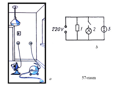
It is not advisable to connect the devices connected to the electric circuit in series without connecting and disconnecting them. For example, serial connection is unsuitable for lighting rooms in the house. Because it is not necessary to turn on the lamps in all rooms at once. When we turn off one, we turn off the others connected in series. Serial connection is also unsuitable for connecting sockets and other appliances. In all cases where power tools need to be connected and disconnected separately from the circuit parallel connection used. 57- at parallel connection of lamp, vacuum cleaner and heater in the picture, 57- b the figure shows a schematic of such a connection. Unda 1-space heater, 2-lamp and 3-vacuum cleaner.
When connected in parallel, the current splits into several networks and resembles a river with several islands in the middle. When talking about parallel connection, the following two terms are usually used: "parallel branching" and "parallel branching node". 1. Electrical voltage in parallel connection of consumers. When connected in parallel, all devices are connected to the same power supply, so the voltage is the same. We can write this as follows:
U = U1 = U2 = U3 =… = Un. (Formula 1)
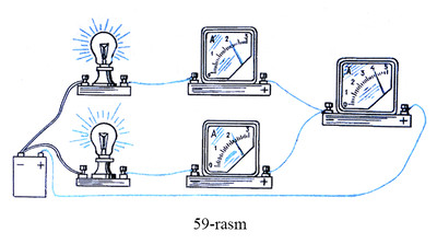
2. The current in a circuit where consumers are connected in parallel. Assemble the electrical circuit shown in Figure 59. Observing the readings of the ammeters, the following conclusion can be drawn: the current in the unbranched part of the chain is equal to the sum of the currents in some of its branches:
I = I1 + I2.
Not if we have two n If there is a consumer, then the current in the network n is equal to the sum of the currents flowing through the consumer:
I = I1 + I2 + I3 +… + In. (Formula 2)
3. Resistance in parallel branching. Two methods are used in the study of physical phenomena: the experimental method, in which the phenomenon is studied on the basis of specific experiments, and the theoretical method, which is studied on the basis of analysis of knowledge obtained based on the results of experiments.
So far we have mostly used the first method. To find the resistance of parallel branching, we use the theoretical method.
It is known from experience that the current in a parallel branch is equal to the sum of the currents in some of its branches (see Equation 2).
Each of the networks has resistance. This resistance R1, R2, R3,…, Rn we define with. We also know that the voltage at all network terminals is the same (see formula 1).
To find the resistance of parallel branching, we apply Ohm's law to the whole network:
I = U / R.
Now we apply Om's law to each of the branches:
I1 = U / R1; THE2 = U / R2; THE3 = U / R3; …, In = U / Rn.
Substituting the values of current in networks and the value of current in parallel branching into formula (2),
U / R = U / R1 + U / R2 + U / R3 +… + U / Rn
we create an equation. The right and left parts of the equation U as,
1 / R = 1 / R1 + 1 / R2 + 1 / R3 +… + 1 / Rn
we form a relationship. The magnitude of the inverse of the resistance is called the conductivity. The resulting formula should read as follows: the conductivity in a parallel network is equal to the sum of the conductances in its networks. 4. What should be the resistance of the voltmeter? A voltmeter is designed to measure the voltage across a certain part of a circuit. It is connected in parallel to this part of the chain. Its connection should not significantly change the current in the circuit. Therefore, the resistance of the voltmeter should be on the floor. Otherwise, the current flowing through it increases the total current in the parallel branch.
Source: Physics 7th grade textbook
Ibn Sina Medical Publishing House, 2002
Notification: CBD oil til kroppen med
Notification: escorts in Modesto
Notification: Dū h̄nạng xe wī
Notification: psilocybin chocolate
Notification: devops professional services
Notification: Magic Mushroom Chocolate Bars
Notification: doitsu fkk
Notification: Booth installation services
Notification: dewahk
Notification: Cambodia Albino Mushrooms – 4 Oz,
Notification: https://www.postandcourier.com/sponsored/phenq-reviews-does-this-diet-pill-actually-work/article_1cdbfb1a-395f-11ee-9d97-33c51303c959.html